I Hacked My Dehumidifier to Control it Over WiFi
See disccusion on Reddit.
—
Many modern devices are connected to the internet – thermostats, light bulbs, vacuum cleaners, you name it. It’s certainly convenient to control your house’s thermostat using your phone, or to have a robot vacuum your house. It’s also easy to take this too far, but it’s still a fun gimmick to control your devices from an app on your smartphone.
Something I’ve been wondering lately, is, how hard would it be to make your own smart devices? They typically harvest lots of data about you which they subsequently transmit over the internet, which is less than ideal for privacy reasons. Instead, if you make your own smart device, you’d have full control over what the device can and can’t do. This means you wouldn’t have to install spyware on your phone or give out all your personal information just to turn on your CO2 monitor.
This CO2 monitor with thousands of positive reviews demanded that I create an account, download their app and allow precise location information before it would report the amount of CO2 in my room. – Andrej Karpathy (I love calculator)
Making my own smart device seemed like a fun challenge. I’ve been teaching myself electronics in the past year, so as a learning project, I wanted to turn one of my “dumb” household appliances into one that could be monitored and controlled remotely.
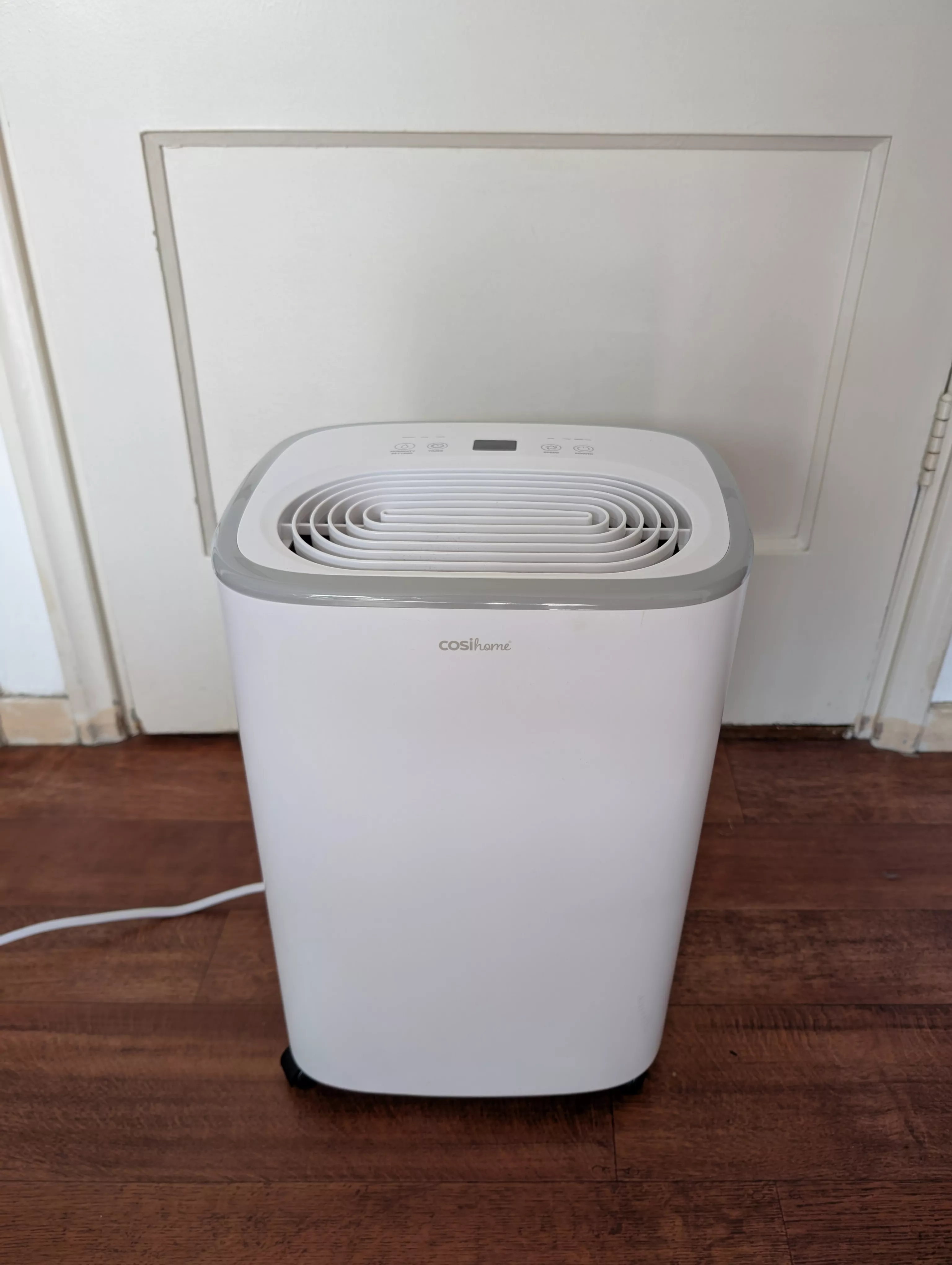
First, I needed to pick a device to work on. I recently bought a dehumidifier, which is a device that extracts moisture from the air to control humidity levels. (I live in a house with a bad humidity problem.) This particular device does not have any native wireless capabilities, so it seemed like a good candidate for my project.
The basic idea would be to turn the device on and off remotely, using some kind of wireless protocol. So, let’s say, I want to turn the dehumidifier on, but I’m too lazy to get off the couch. All I would need to do to control it is to send a command using my phone or laptop. This way, I don’t have to walk five meters, which means I can preserve precious energy for other tasks.
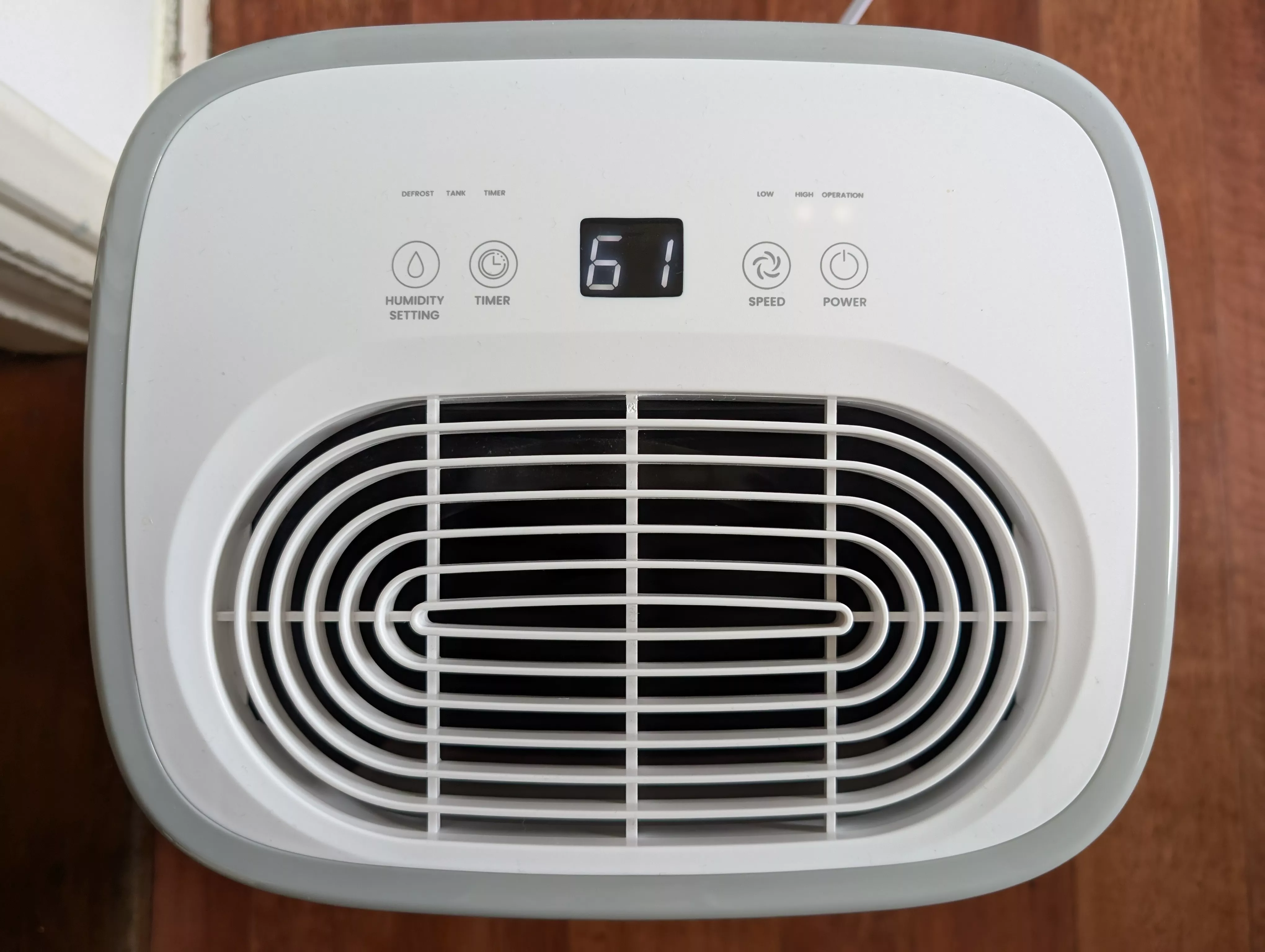
The first order of business was to open the dehumidifier up to see what we’re dealing with. On the top of device is a numeric display, four buttons, and some small LEDs showing various status information, like the speed of the fan, or whether the water tank needs to be emptied.
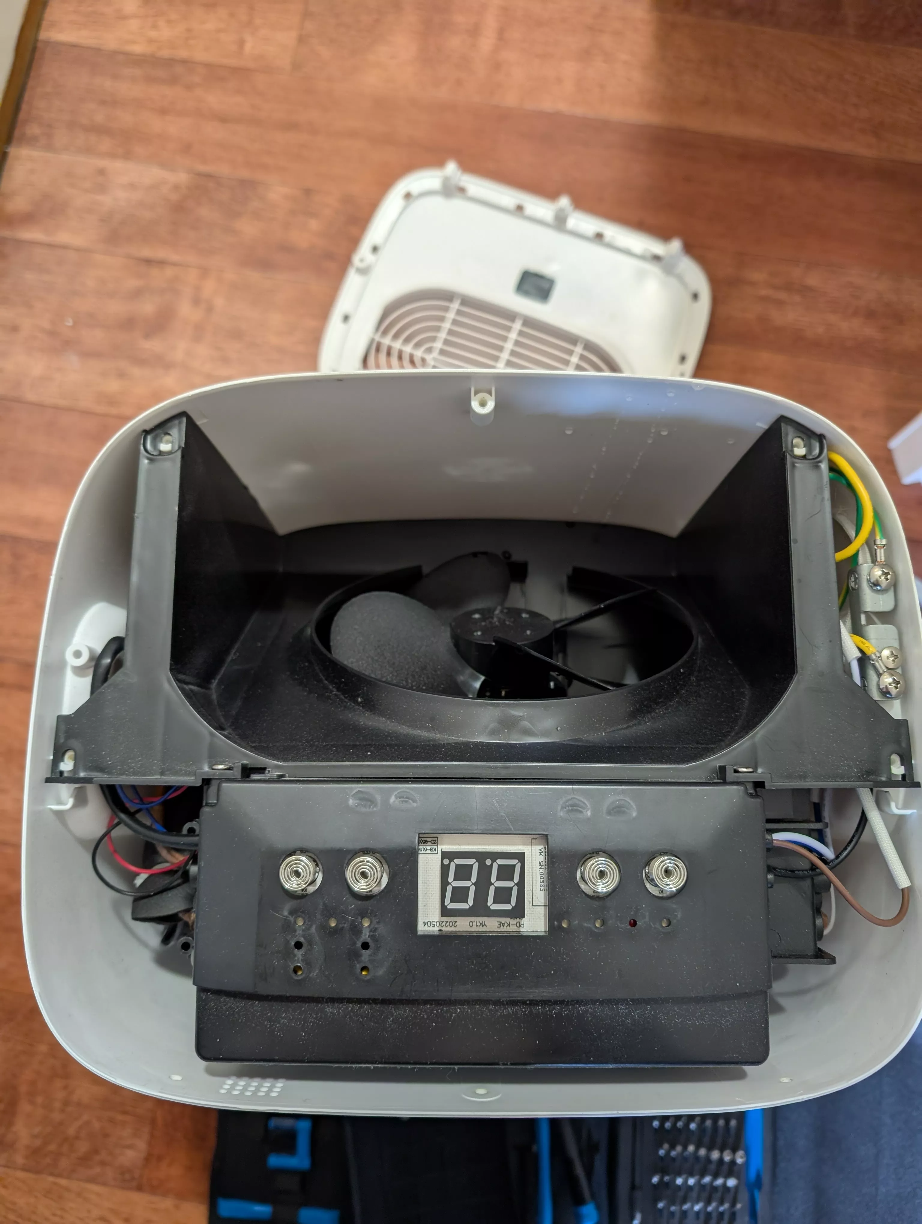
After removing about ten screws and unlocking some plastic clips, the inside of the device looks like this. The image shows a fan at the top, and on the bottom an enclosure with an LED screen (for displaying the humidity level), next to four spring-controlled buttons for interacting with the device.
Just for some background, here’s the basic TL;DR for how a dehumidifier works. First, it uses a fan to draw in humid air. This air is passed over a cooling surface, which condenses the moisture into liquid water. The condensed water collects in a tank or is drained away. After the moisture is removed, the now-dry air is reheated and released back into the room by the fan. Obviously, this mechanism is actuated by a bunch of electronic components in the device, which we can access by opening it up.
Coming back to the disassembling, we can see the main circuitry of the device when we remove its enclosure:
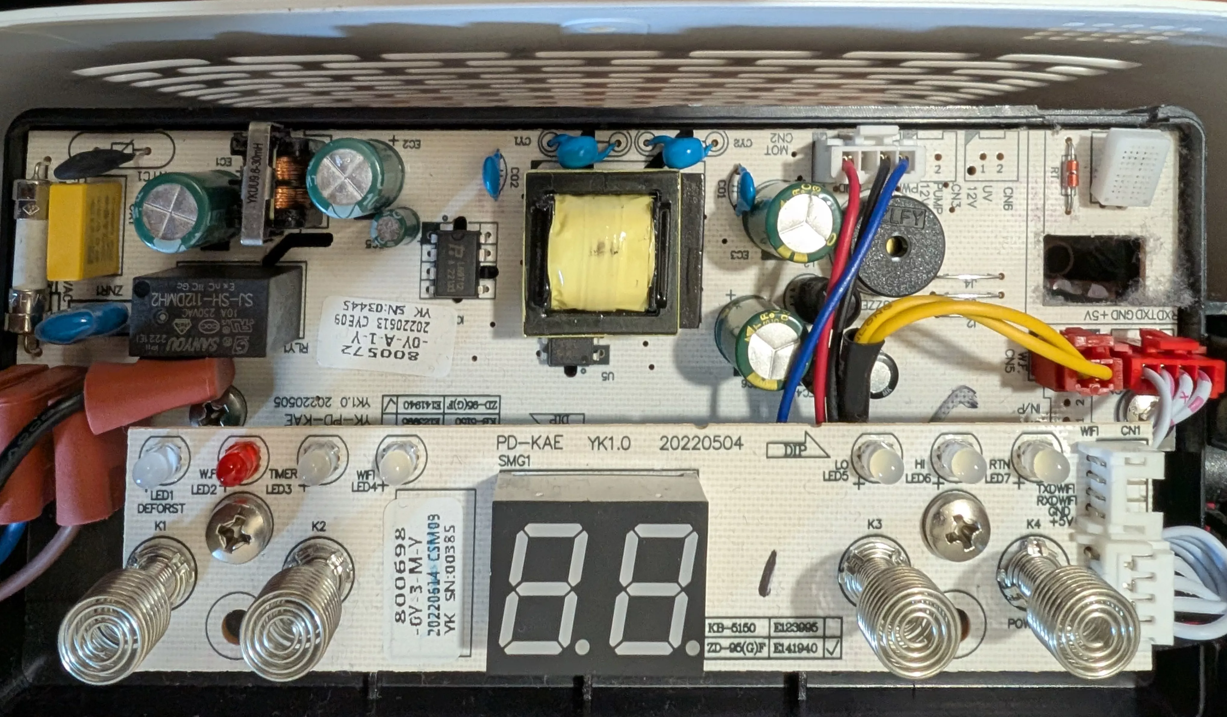
Much of the circuitry in the top of the image is dedicated to stepping down a mains 220-240 Volt AC input into a lower voltage DC output. The mains power comes in from the left of the image and gets transformed to a 5V DC power required for the fan and other things like the button controls.
The main thing I was interested in though, were the spring-based buttons next to the LED display. These four springs correspond to the four buttons the user can press on the top of the device. They are normally covered with a plastic surface, and actuated by pressing down on the plastic at the location of the button.
In order not to over-complicate things, I wanted to focus on controlling the power button specifically. My idea was as follows: If I could somehow simulate the electrical signal that the spring connected to the power button generates, I could use this to remotely trigger the on/off switch.
To find out the mechanism by which the power button operates, I first had to figure out what the spring was connected to on the other side of the PCB. Disconnecting the PCB and turning it over reveals the main microcontroller as well as the wiring around it:
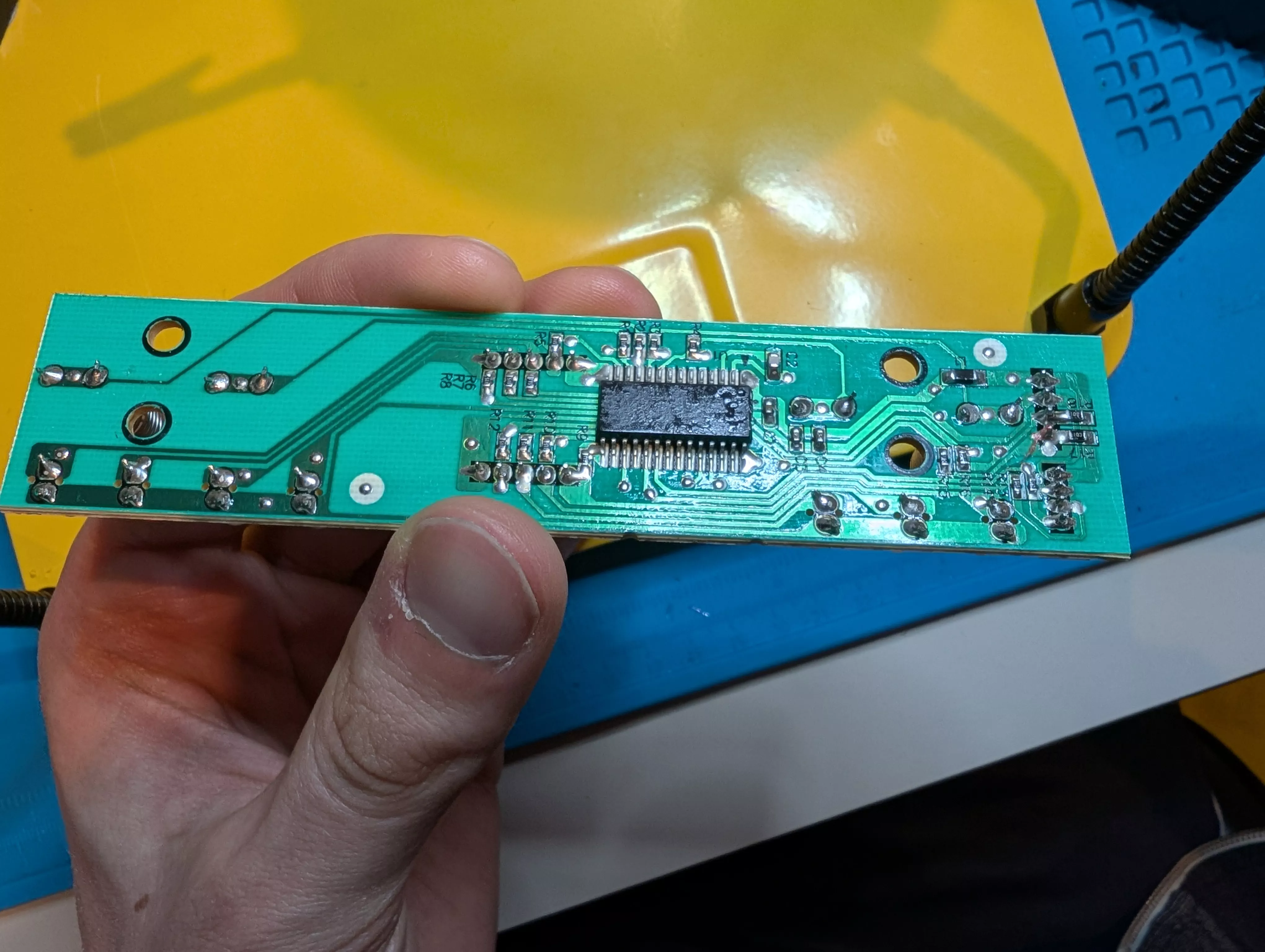
This board is relatively straightforward. You have a microcontroller in the middle, which acts as the brains of the device, sending and receiving signals to other components. Then, you mostly have a bunch of resistors and capacitors around the microcontroller, with traces leading to the LEDs and buttons on the other side of the board. It’s hard to figure out exactly what the microcontroller is doing (it’s quite literally a black box) so instead, we can look at the wiring to and from the chip to figure out what is going on.1
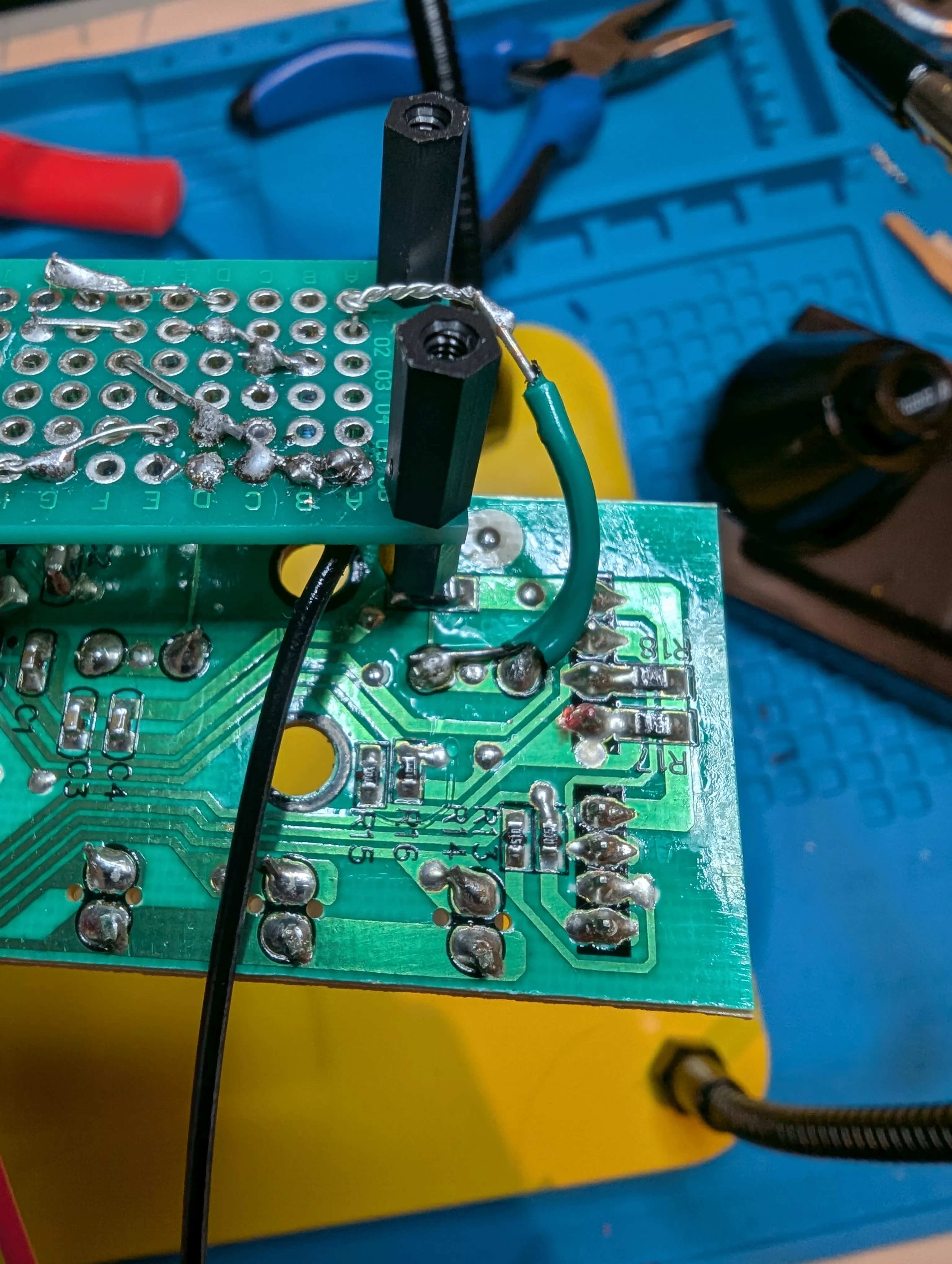
We can start by looking at the points where the springs are connected, shown in the image below. The connection on the right leads to the spring-based power button we’re interested in.
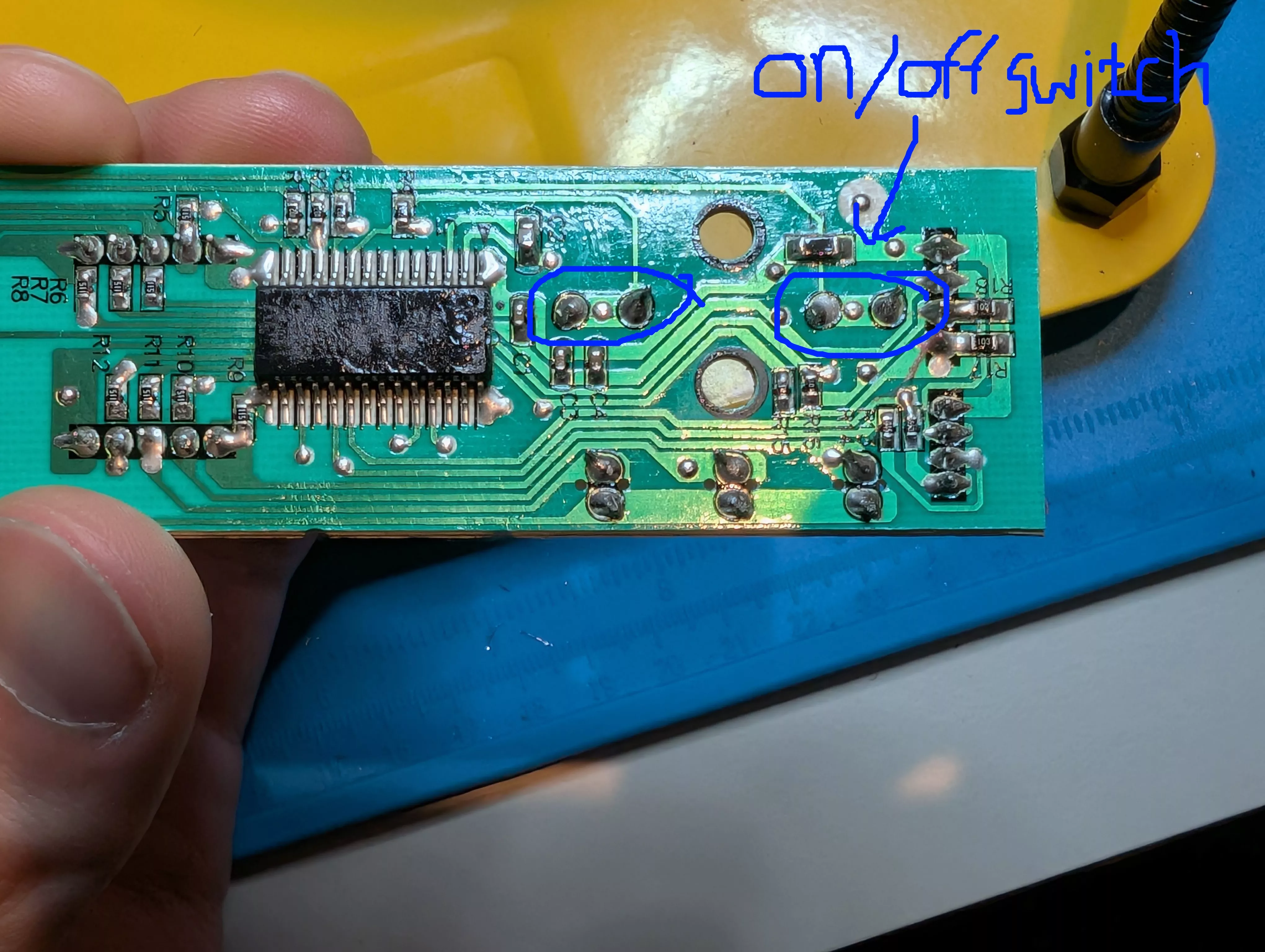
If you look closely at the image, there is a connection (also called a trace) along the top of the board, coming from the spring connection, through a resistor, and into the microcontroller. What this most likely means is that the power signal for the device gets sent on this trace. Therefore, we can start by manually injecting a signal here to figure out how we can trigger the power signal ourselves.
I was definitely confused by the spring-based buttons, and it took me a while to figure out how they worked. At first I thought that pressing down on the spring would somehow make contact with an underlying conductive path, which would pull a specific signal high or low (depending on what the microcontroller responds to). But one of the most confusing things was that I could trigger the switch simply by making contact with the pads, even without using any electrical signals. For example, by touching the pad with the leads of my multimeter when it was turned off, or with my finger. It was clear that somehow, the switch was extremely sensitive to any kind of contact or electrical signal, no matter how small.
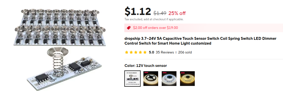
After some research, I figured out the spring is actually a capacitive touch sensor. They’re a bit confusing to understand, but the basic mechanism is that when your finger makes contact with the button, it forms a tiny capacitor with the spring, which is picked up by the circuit and interpreted as a button press. These kinds of sensors are commonly used for appliances that require some kind of “touch” buttons as a replacement for mechanical push switches.
Doing an online search quickly revealed similar looking sensors, like this product from AliExpress:
Unfortunately, it’s apparently not straightforward to control these capacitive touch sensors if you want to modify them. Luckily, I found this great YouTube video that shows a circuit design which is capable of controlling them nonetheless. This is what the circuit diagram looks like:

The basic idea is that the two 1N4148 diodes act as switches. When the mechanical switch is closed, the two diodes are forward biased and pass a tiny bit of current to the capacitive sensor, which triggers it. When the switch is open, the point between the two diodes has very high impedance, and no current can pass. The video explains the circuit in more detail.
I put together a breadboard prototype and lo and behold, I was now able to successfully trigger the switch!
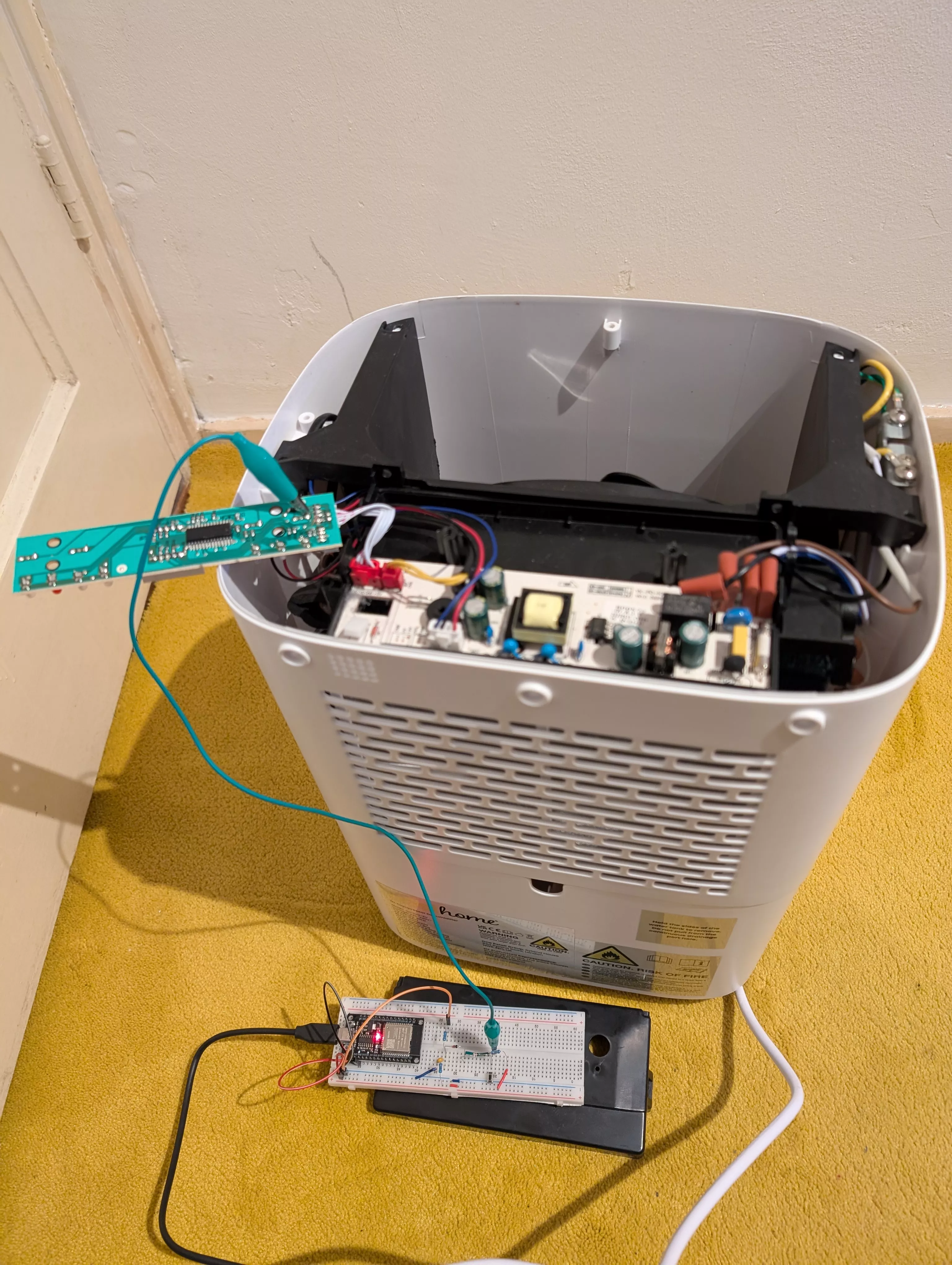
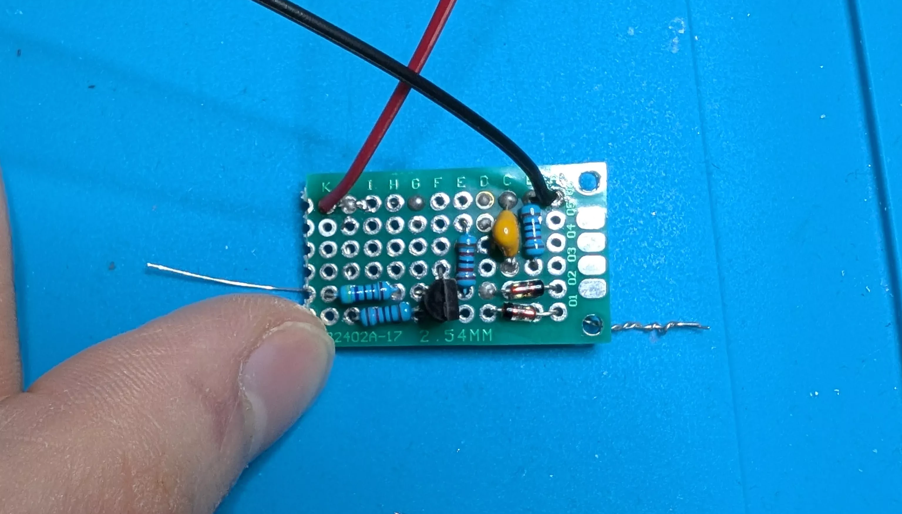
I added a 2n3904 transistor to the circuit to act as an electronic switch rather than a mechanical one, with an added resistor at the base pin.2 I then put all the components on a perfboard and soldered them together. The result looks like this:
Now I just needed a way to send a signal to the dehumidifier wirelessly. After some research, I settled on the ESP32 microcontroller. This device is somewhat similar to an Arduino, but with integrated Bluetooth and WiFi. You can write custom programs in, for example, C or Python, and load them onto the microcontroller using a USB connection. I was actually amazed to find out how cheap these little devices are – you can pick them up for not much more than $5 on AliExpress.
The program for the ESP32 is quite simple. It spawns a basic HTTP server which allows it to receive incoming requests over the WiFi network. Whenever it receives a request, it sends a signal from one of its GPIO pins (in this case GPIO 5) to the base of the transistor to trigger it, which sends the signal to the capacitive sensor through the custom circuit I just showed you.
The final circuit diagram looks like this:

I actually found out that there’s a mistake in this circuit, which I found out only after I soldered it in place. Luckily for me, it still worked.3
After some more testing to verify that things worked correctly, it was time to solder everything together. The perfboard needs to connect to the ESP32, and they both need to receive 5V power from the dehumidifier. Luckily for me, there was an unused port on the dehumidifier PCB which gave me a 5V power source.4
I also had to find a place to mount the new components. There was a neat little empty space under the PCB that could nicely fit all my components.
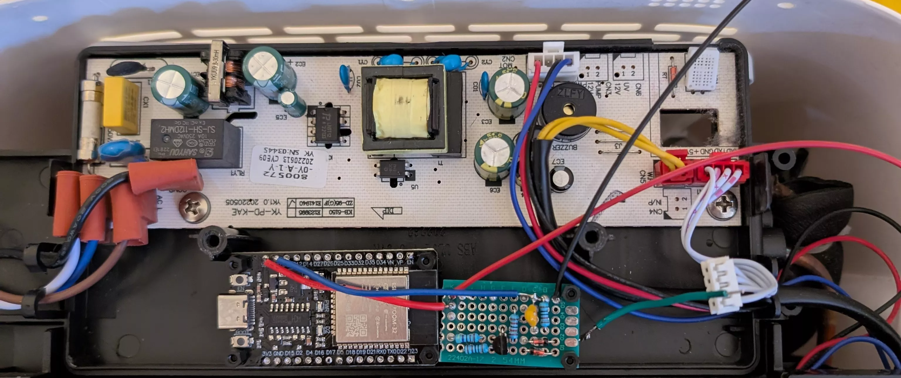
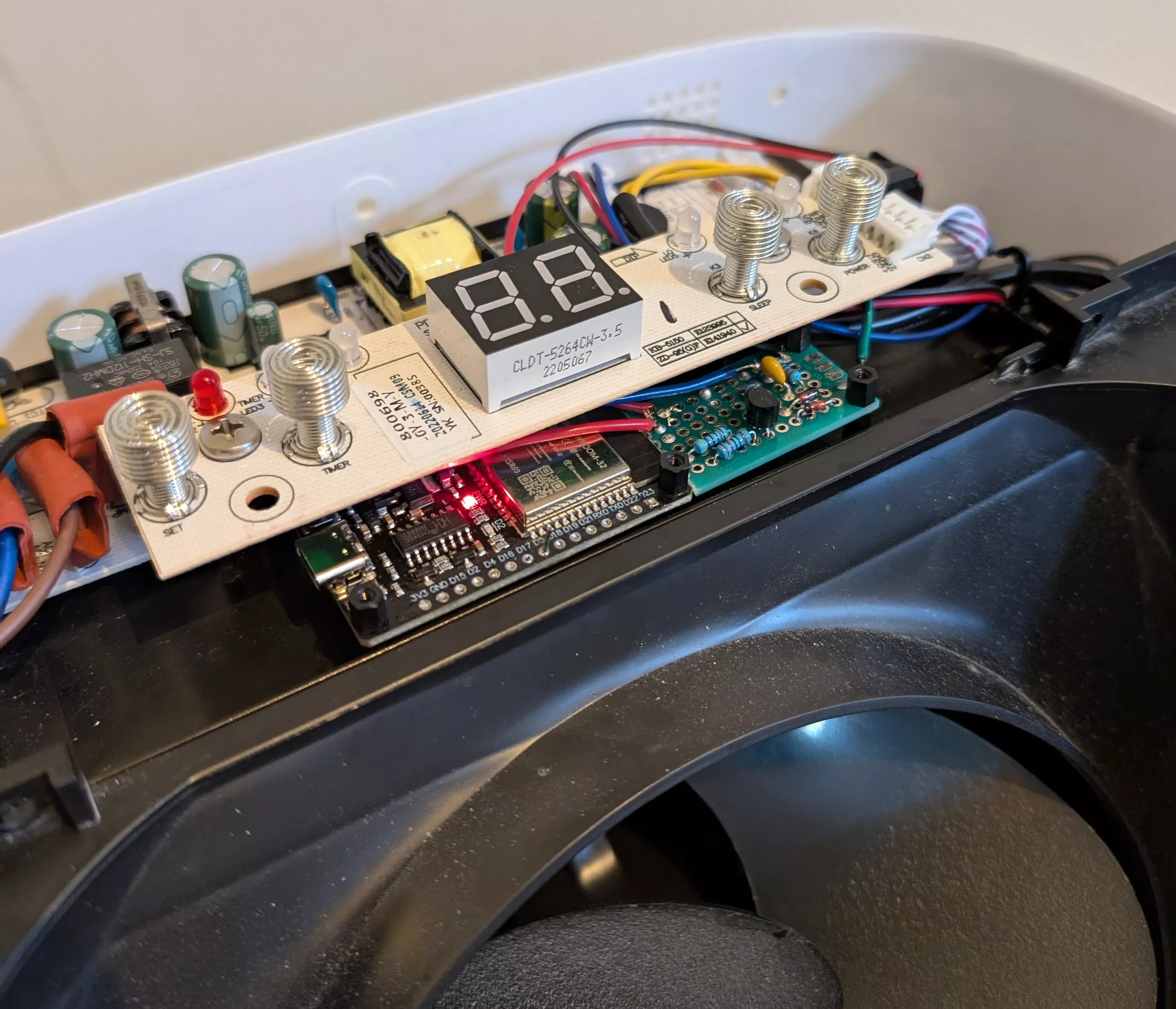
After putting back the other PCB, the new components now snugly fit into the box:
I created a simple web app (which is just a big green button) for controlling the device. It works surprisingly well! Here’s a demo of the final result:
Conclusion
This was a fun project to work on. If I want to expand the functionality, I could add more sensors to the ESP32, e.g. for temperature and humidity, and turn the web interface into a proper dashboard. I have a bag of cheap sensors from AliExpress lying around – maybe I’ll try connecting those at some point.
It can be pretty intimidating to modify a device like this because there’s lots of unknown unknowns (who knows what you could break?), especially for someone like me with limited experience in electronics. Needless to say, I was pleasantly surprised by how well the whole thing works! It’s great to see all the individual pieces come together like that.
-
Another option may have been to listen on the UART communication sent on the Rx and Tx pins to figure out what the microcontroller is doing. ↩
-
I actually had to try out a bunch of different resistor values to find one that sufficiently saturated the transistor. I initially tried to calculate this resistor value using theory, but eventually came to the conclusion it was much more effective to simply measure the voltage drop across the transistor using a multimeter in order to find the best resistor value. ↩
-
I had contact with Leo, the author of the YouTube video, and apparently I used his circuit in a way that he didn’t intend at all. This is because his circuit was designed to connect capacitively to the circuit, not with a direct connection, which was what I was using. But somehow, it still works! I asked Claude 3.7 to analyze this circuit and it says transient voltage changes may be the reason why this ciruit still works. According to Leo, a better solution would be to put a small capacitor (20 pF or so) in series with the wire to the sensor, to block DC to the dehumidifier PCB. Anyway, you should probably take my circuit design with a grain of salt, because I barely know what I’m doing. ↩
-
Fun fact: this port was labeled “WFI” (i.e. WiFi?). Perhaps the original design of the dehumidifier actually included WiFi control! ↩